The Find
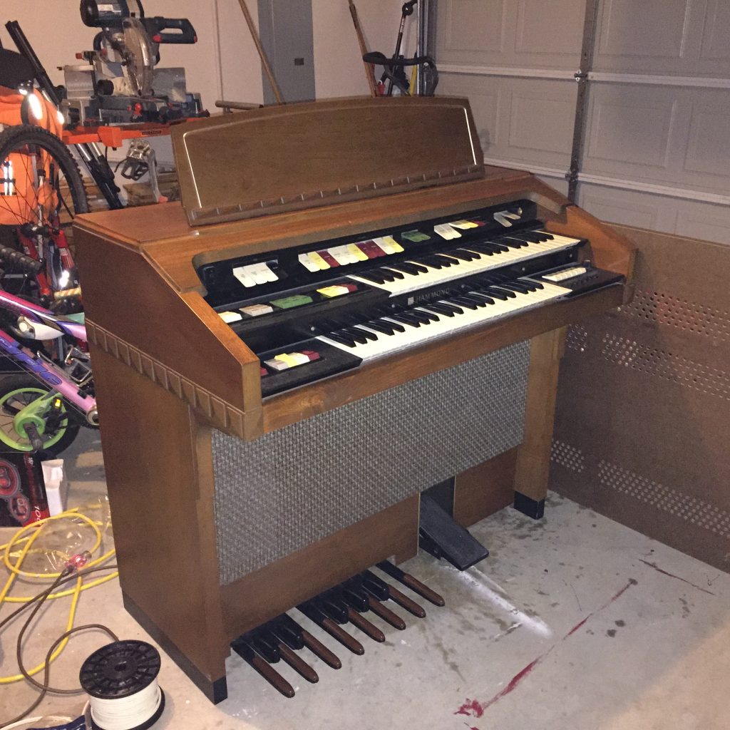
A very nice retired couple was giving away a Hammond N-222 on Freecycle (I love Freecycle!). So, I asked my friend, Sam, to help me bring it home. We barely managed to wedge it into a Prius V, but eventually got it back to my garage.
After a bit of research, I learned that this model has a built-in Leslie speaker. The organ wasn’t worth much, plus a few of the keys were non-functional. I also learned that over the years, guitarists have used Leslie cabinets to add a tremolo effect to their rig. I thought building a speaker cabinet out of the parts I could salvage from this organ sounded like a fun project.
What I wanted to achieve that differed from similar projects was to retain some of the original character and visual design elements of the organ.
The Disassembly
It has taken all my will power to avoid the organ harvesting puns while writing this. As I was taking the organ apart, I got a better idea of which materials from the organ I could use to build the speaker cabinet, including some buttons, knobs and the Hammond nameplate. I was a bit disappointed to discover that much of the organ’s cabinet was made of particleboard. The parts that were either plywood or solid wood were not substantial enough to be used in building the speaker cabinet. At this point it looked like I would need to construct a new box from other materials.
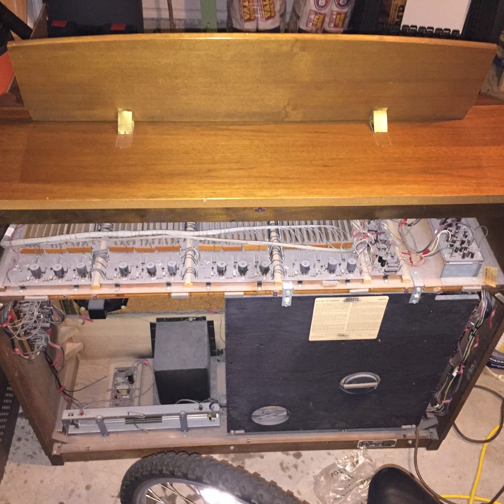


I also discovered a spring reverb unit in the bottom of the cabinet. I had planned to incorporate this into the design, but I decided to keep things simple for this build. So, I’ll do something with the reverb tank in another project.

The Design
Once disassembled, I put some of the materials together to get a sense of the aesthetic. I think these elements together really preserve the look of the organ.

I wasn’t sure how to orient the parts in the cabinet, but here’s a first take at what I thought the resulting box might look like. If you can’t see the lighter strokes, I’d intended to have the flat sides of the spinning cylinder face the front and rear of the cabinet.

After some careful measuring and some reflection on how the sound will get out of the box, I changed the orientation of the sound wheel, and therefore the entire enclosure. In my research, I found varying opinions on geometry, construction techniques and preferred materials. I settled on 3/4″ plywood for the structure of the box, as it would result in a really strong box. One of my favorite design tools of late is OpenSCAD. I’ve been using it to visualize a lot of projects, and I thought it’d be useful to get accurate dimensions for this project. I’ve put my OpenSCAD files online if you’d like to take a peek, or use them for your own project.

Lastly, the 8″ speaker that came with the organ was a rather non-descript and blah-sounding affair. I chose to upgrade it with an actual guitar speaker. I found an 8″ Celestion Eight Fifteen (15W) speaker on Amazon warehouse for under $30. It had good reviews, so it seemed like it was worth a try.
The Materials
I got lucky on the plywood front. My friend, Eddie, had lots of scrap 3/4″ plywood and was generous in letting me use that instead of buying new material. For the covering, I wanted to get tolex that would be similar in color to the wood of the organ. Mojotone Brown Marvel Leather seemed to be the right color, and it happened to be on sale!

I opted for black hardware to match the nameplate, and picked Reliable Hardware cabinet corners. I purchased a set of 3-screw corners for the rear of the cabinet and a set of 2-screw wrap around corners for the front. I decided against using straps, because of the size of the cabinet. I didn’t think adding straps would make lifting and carrying the cabinet any easier than picking it up from the bottom.
The Build
Step 1: Checking That the Motors Work
Before ordering parts, I wanted to make sure that I knew how the motor worked and what would be required to switch between speeds. I quickly wired up the motors to make sure they worked and that I understood how to switch between them.

Rather than having a variable speed motor, the system has 2 motors, one for each speed setting. This was unexpected, but led to a simple solution. I thought I would have a separate power switch and Leslie speed control. But my friend, Ben, helped me realize I could do everything I needed to do with a single 3-position switch.
This was my first project that used AC power, and of course, I forgot about a fuse! That was quickly remedied by using a fused AC power connector on the rear panel.
Step 2: Designing the Leslie Control and Power to the Motors
Since I wanted to use the original control button for the Leslie, I had to figure out a way to convert the button’s angular motion into the linear motion of a switch. First, I thought of using a toggle switch underneath the button, but Ben suggested a 3-position sliding switch instead. I figured I could 3-D print the parts I needed to make this work and set to work devising a harness for the switch and original button.
To incorporate the old Hammond buttons, I selected the one marked “Leslie Slow/Fast” to control the motor selection. I went to my local makerspace, thelab.ms, and 3D printed a housing and mechanism to actuate the 3 position switch. The switch cover plate for the button I 3D printed using a wood-impregnated filament that could be sanded and painted to match the cabinet. However, this proved to be too brittle at the dimensions I used, and so I opted to print in black ABS.


Step 3: Building the Cabinet Box.
Eddie cut the boards down to size on a table saw for me. then, I clamped the parts together to make sure the measurements were close enough. Things were really starting to take shape!


With everything test fitted, I decided to try out the sound and see if there was a discernible difference if the back of the cabinet were open or sealed. I preferred the sound of a sealed enclosure. Here’s a video showing the Leslie in action in both slow and fast speeds.
Satisfied with the resultant sound, it was time to put it all together. Eddie recommended doweling the walls of the enclosure for added strength. First, I glued and screwed the Leslie assembly to the bottom panel of the enclosure. Then, I doweled the side panels and glued it all up. Once it was dry, I screwed the top panel into the top of the Leslie assembly. To say the least, it is a solid build!


After constructing the box, I sanded the edges to even them up, then I hit the edges with a 3/8″ roundover bit in my router. The cabinet corner specs indicated a 1/2″ inner diameter, but it looked a bit smaller to me. The 3/8″ bit was a perfect fit.
Step 4: Covering the Cabinet in Tolex
I ordered a single yard length of the tolex, which had a 54″ width. I underestimated a bit, so I decide that the rear panel would be covered in grill cloth instead of tolex. I am happy with how it turned out despite the error in estimation. The hard parts with the tolex were cutting the corners. The How-to video from Reliable Hardware shows mitering the corners, but you have to be careful not to overshoot the corners or the cuts show. Sadly, I missed a few of them.


Step 5: Final Wiring of the Motors and Speaker
The next step was to do the final wiring of the speaker and motors. This was my first time using heat shrink tubing. This stuff is great!

Phase 6: The Finishing Touches
I wasn’t sure how I’d cut down the nameplate, but I had a lot of room for error. The final piece only needed to be about 12″ long, and I had about 36″ of material to work with. My first attempt was to use metal snips. It cut easily, but because the nameplate is c-shaped in cross-section, the snips bent the edges. The metal appears to be aluminum, so I decided to try a cutting wheel on the Dremel. This produced a much better edge, but was hard to steady. I mounted the Dremel on the press stand and elevated the nameplate to the level of the cutting wheel. I was then able to slide the nameplate across the wheel in a smooth fashion. After making the cut, I tried smoothing things out with a grinding bit, but it made the edge uneven. I then tried some medium grit sandpaper, and that worked well.


The Finished Project


Overall, I’m very pleased with the look and sound of this cabinet. I’m really impressed with the Celestion Eight Fifteen speaker. It has a lot of low-end for such a small speaker.
Sound Samples
Some Issues
- When the cylinder stops spinning, there isn’t a way to make sure the opening points toward the front of the cabinet. I’ve thought through a few ideas, but most are overly complex and require a lot of effort.
- Because I wanted to keep the cabinet as compact and as simple as possible, I didn’t design in a way to replace the speaker. If it every blows, I’ll have to rip apart the cabinet.
Lessons Learned
- Slow down when cutting the mitered corners of the tolex
- Fill in any surface divots or other irregularities before applying the tolex. There’s a good chance they’ll show through.
- Don’t touch bare AC wire connection points when they are plugged in.
Parts List
| Description |
Cost of needed parts only
|
| 3/4″ Plywood for body | $0.00 |
| 1/4″ switchcraft panel mount jack | $3.60 |
| recessed jack panel | $4.99 |
| AC power wiring with ground 14/3, 2′ | $2.00 |
| speed switch (6 contact 3-position switch “on-off-on”) | $1.28 |
| 3 point guitar cabinet corners | $6.06 |
| 2 point guitar cabinet corners (wrap around) | $8.96 |
| panel mount power connector w/ fuse | $1.65 |
| Celestion Eight 15 8 Ohm speaker | $21.65 |
| rubber feet | $2.49 |
| #8 1/2″ metal oxide wood screws | $2.63 |
| Mojotone Marvel Leather Tolex | $18.23 |
| DAP Contact Cement | $18.50 |
| total | $92.03 |
Acknowledgements
I’d like to thank Sam for not blinking when I asked him for help picking up the organ. Big thanks to Eddie for donating the plywood and for cutting the big pieces on his table saw, as well as for suggesting the dowels (and letting me borrow the doweling kit). Finally, I’d like to thank Ben for helping me figure out the electrical bits.